Search This Blog

Studebaker M15A-20 "Mr. Potato Head"

Monday, July 30, 2012

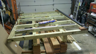
New Bed Started


 This is the substructure made of 4x4s. MCA treated SYP. Frame runners are two 4x4s stacked. Joists are six 4x4s. Side 4x4s are notched with the joists. All attached together with 1/2" x 6" SS lag bolts.

 This how the Deck Grabber goes on. It screws to the joists and then is screwed to the deck boards when they are installed.

 Here is a mock-up of a deck board and the angle iron edge. Deck board will actually go all the way to the edge of substructure. 3/8" x 6" flat head SS bolts will attach all the layers together; substructure side boards, substructure joists, deck boards, and angle iron.

 Closeup of the notching

 SS lag bolts inset

 One screw in the Grabber. These screws are the Lox type.

 View of inside of Grabber

Box of Grabber and screws

Brian's Baby Comes Home


Monday, July 23, 2012

Stereo Installation


 Panel installed, concealing the stereo. Can't really see the wired remote but it is mounted on the drivers door near the door latch handle.

 Panel removed for access of stereo. Wires are extension cables that go to the glove box where I can plug in a thumb drive or other audio device like a digital player. I now use a real dinky thumb drive that just plugs into the front of the stereo.

Back of panel. magnets are JB Welded in place and covered with tape to protect the dash paint from scratches. I have since got a tip from STF to replace the tape with that soft stuff the coats tool handles. On the face of the panel I cut screws off and JB Welded them in place so it looks like the panel is screwed on...

Wednesday, June 20, 2012

Valve Adjustment

I now have (56,001.7 - 54,349.3) 1,652.4 miles on this new rebuild and it is time to adjust the valves after the cam, lifters, and valves have broken in. Valve clearance is supposed to be 0.016" but I found all of them to be between 0.017" and 0.018" so I did not adjust them here are the as measured clearances:

SEQ
EC/IO
ADJUST
CLEARANCE
1
1I
6I
0.018”
3
5I
2I
0.017”
5
3I
4I
0.017”
6
6I
1I
0.0175”
8
2I
5I
0.018”
9
4I
3I
0.018”
7
1E
6E
0.018”
10
5E
2E
0.018”
2
3E
4E
0.018”
4
6E
1E
0.018”
11
2E
5E
0.018”
12
4E
3E
0.0175”

I also did a compression test on all cylinders:

CYLINDER
PSI
1
104
2
104
3
102
4
104
5
105
6
110

All six plugs look the same

 Insulators bright white and ground electrode light gray

Manifold and valve covers removed

 Front bank

 Rear bank


Sunday, June 17, 2012

Fathers Day Sully Car Show

Awesome day at Sully. They had over 400 cars. About 4 Stude cars showed and my truck was put in the heavy commercial category.

 Before all the cars showed

 MPH waited to check in

 Oldies cheking in

 Lots of Model A's

 And the occasional Duece-in-a-half

 More military

 191 Harley

 A Caddy like the one we had when we were kids

 The five Stude cars that showed

 Another view

 MPH


Flee Market had lots of old stuff
 
The trophy I won

Cars and live music


Friday, June 15, 2012

New Doors!

Finally got the new doors installed on the truck. One door I bought from CA on ebay and the other I bought from Vern in KS. Did a little MIG work on the bottoms, some paint, new cat whiskers, and rubber. Ride is so much nicer with out all the noise from the windows flopping around in the doors. Also added a drivers side lock...


Friday, May 4, 2012

Throttle Shaft Bushing Install

I bought a reamer kit to install throttle shaft bushings in the throttle body. The throttle body is made of cast steel and eventually wears. This kit comes with the reamer and four 5/16" bushings. Here it is on ebay:

http://www.ebay.com/itm/Carburetor-5-16-Throttle-Shaft-Bushing-Repair-Kit-Made-in-USA-Bushings-Screws-/230761299891?pt=Motors_Automotive_Tools&hash=item35ba71ffb3&vxp=mtr


It is assumed that the reamer in the kit will be used with machinery to align the reamer properly. I don't have this equipment but because the reamer shaft is 5/16" in diameter it can be used as a pilot. The key is to grind cutting edges on the inside edges of the reamer:


Then, because the reamer is now being pulled not pushed there needs to be a place to grip the reamer with a tap holder:

Slide the reamer into the throttle body, attach the tap handle and start reaming:

I use a cutting fluid but oil came be used:

Apply to the cutting surfaces:

I reamed nearly all the way through then ream the other side using the nearly reamed hole on the other side as the pilot hole:

After reaming the second hole all the way I finish reaming the first hole. Then I clean the holes with denatured alcohol and start inserting the first bushing. After starting the first bushing I apply some permanent Loctite:

I press the bushing in until it bottoms out. Then I align another bushing and press that into the bore pushing the first bushing until it pokes out into the bore:

Then I cut off the excess bushing:

And file smooth:


I then trim the inside end of the bushing to be flush with the curvature of the carb bore. Then do the same on the other side...