
To eliminate this pitting, a modification can be accomplished to reduce the contact current from 600 ma to 600 ma. The solution is performed by adding a MOSFET transistors to carry the current. The procedure is as follows:
1. Break the heater connections
a. Modify the contact stack
b. Gold plate the contacts
2. Build and install circuit board
a. Cut board and cut the traces
b. Solder on MOSFETs and resistor
c. Epoxy board to meter
3. Wire the circuit board
4. Test and adjust the meter

Reference pictures


Break heater connections
To make the break in the circuit between the contacts and the heating elements the following is done:

Drill out the rivet holding the contact in place

Contact & heater assembly removed from gauge

Contact & heater assembly disassembled


I decided to use Litz wire for connections "A" and "B" because it is a very flexible wire


Build and install circuit board


Wire circuit board

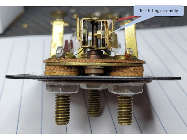
Test the meter
Testing consists of hooking up the meter and sending unit on the bench with a 6 volt battery to power the meter/sender. The two meter arms are iteratively adjusted to get the meter needle to land on the full mark when the sending unit arm is in the full position and the empty mark with the arm in the empty position.
The big problem is to determine the sending unit's full and empty positions. My current plan is to attach a weight to the float so it drops to the bottom of the tank and measure the sender resistance. To measure full I can just fill the tank and measure the sender resistance. I then can adjust the sender's arm for each position to get the resistance for testing the meter.
When testing it is a good idea to connect a ammeter meter in series with the power to the meter. This is a good way to make sure everything is connected correctly and lets you a way to monitor the contact open/close activity. When everything is connected and power is applied the gauge will take some times to settle. The meter should be drawing 200-250 ma. Initially the gauge is settled when the contacts open and the ammeter meter shows zero current for a moment. The contacts should open/close at a rate of once every 5 seconds.


Test setup


Note ammeter shows ~300 ma.


