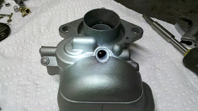
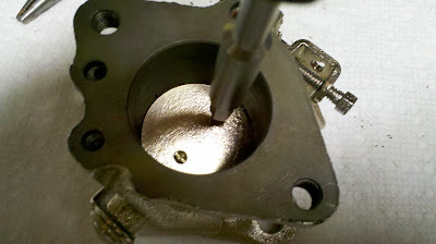
With all parts cleaned up, body painted, and some parts Nickel plated, assembly and adjustment is next. I decided to make fabric reinforced neoprene gaskets to see if they work better than what came in the rebuild kit. The gaskets supplied crush over time and everything needed to be re-tightened and they wicked fuel.
All the parts to put together the carburetor less the assembly screws, where did they go?
First to install is the accelerator pump inlet check valve ball and retainer
Here is the accelerator pump well where the valve goes
Check valve installed
Next is the accelerator pump outlet check valve ball and retainer screw
The accelerator pump outlet check valve well
Accelerator pump outlet check valve installed
Next is the accelerator pump jet and cover screw
Accelerator pump jet well
Accelerator pump jet installed
Accelerator pump jet cover screw installed
Main jet
Main jet well
Main jet installed
Idle well jet
Idle well
Idle well jet installed
Main discharge jet
Main discharge well
Main discharge jet installed
Main discharge well cover screw
Main discharge well
Main discharge cover screw installed
Throttle body main components
Throttle shaft installed and throttle plat in place
Install throttle plate retaining screws
Throttle shaft end retaining screw and slave actuator
Throttle shaft end retaining screw and slave actuator installed
Loosen both screws and close throttle plate all the way to seat the throttle plate. Work the throttle shaft back and forth to verify smooth operation. Next loosen one screw.
On the opposite side dab some thread locker into the screw hole then tighten the screw. repeat with the other screw.
Install the idle mixture adjusting screw and spring
Vacuum advance fitting
Vacuum advance fitting with thread sealer and flare fitting ready for installation. Adding the flare fitting before installing helps strengthen the fitting for installation
Throttle body complete
Air horn housing and choke components
Install spring onto fast idle cam and install cam
Install choke shaft and vacuum unloader piston. Use a pin to align the hole in the piston with the actuator and then insert the retaining pin
Vacuum unloader piston installed
Install fast idle link
Install unloader arm
Install choke cover plate
Install choke cover gasket
Install choke plate and retaining screws
Loosen one screw and apply a dab of thread locker to the screw hole. Tighten screw and remove excess thread locker. Do the same to the other retaining screw.
Install choke bi-metal actuator spring
Install choke cover
Install choke cover retaining screws and clips
Bowl cover and components
Assemble main jet metering rod with spring and link
Assemble accelerator pump actuator linkage
Install accelerator pump linkage on bowl cover
Install main metering rod and linkage into bowl cover
Install accelerator pump plunger and link. Then install link retaining clip
Bowl vent valve and hinge pin. The old valve sealing material was old and dry so I replaced it with fabric reinforced neoprene.
Install bowl vent valve
Float valve seat
Install float valve seat
Float, float valve and retaining pin
Float valve installed
Install float and retaining pin
Fuel inlet screen and cover screw
Screen installed. then install cover screw with gasket
Install metering rod vacuum piston on metering rod link
Insert accelerator pump and metering rod piston springs into their wells
Install bowl cover carefully aligning the metering rod, metering rod vacuum piston and accelerator pump plunger into carburetor body
Install carburetor body/throttle body gasket
Mate carburetor body with throttle body and attach with retaining screws
Throttle body attached
Don't forget the bowl vent valve spring... And install the throttle shaft link.
Apply the carburetor body/air horn gasket
Attach the airhorn with retaining screws
Assemble the fast idle link
Install fast idle link
Cover and retaining screw
Cover installed
Assembled carburetor
Assembled carburetor
Adjustment instructions and adjustment tools
Remove and invert bowl cover and adjust float to specification of 1/4"
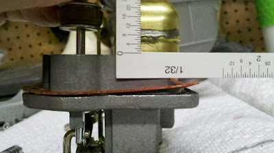
Return bowl cover upright and adjust to specification of 1.2"
Measuring the accelerator upstroke dimension
Measuring the accelerator pump down stroke dimension. The difference between these two measurements should be 17/64"
Remove metering rod and replace with adjusting tool and verify proper dimension. The edge of the gauge should just touch the pin.
Close throttle plate on 0.030" wire gauge
Check bowl vent valve dimension to be between 0.0005" and 0.015"
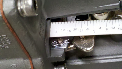
Measure fat idle with a 0.054" wire gauge
Insert 3/16" gauge into choke plate/airhorn bore to measure full throttle unloader specification


No comments:
Post a Comment